How to Build a Gaming PC in 2026: Complete Step-by-Step Guide
Learn how to build a gaming PC step by step, choose compatible components, install the processor, RAM, SSD, and graphics card, and complete your first boot.
Building a gaming PC is much easier when the work is done in a deliberate order. Plan compatibility first, prepare the motherboard outside the case, install the major components methodically, verify every power and front-panel connection, then perform the first boot before finishing cosmetic cable management. This complete guide covers the parts list, compatibility checks, tools, assembly, BIOS, troubleshooting and a sample AM5 gaming configuration.
Components required to build a gaming PC
A complete desktop is built from several subsystems that must work together electrically, physically and thermally. Your exact parts can vary, but most gaming PCs need the following core groups.
Executes game logic, operating-system work and general computation.
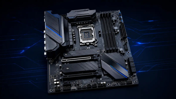
Shop processors →PlatformMotherboardConnects the CPU, memory, storage, GPU, fans, front I/O and expansion devices.
Shop motherboards →MemoryRAMProvides high-speed working memory for Windows, games and applications.
Shop memory →StorageSSD / storageStores the operating system, games, applications and personal files.
Shop storage →GraphicsGraphics cardRenders the images shown on your display and accelerates supported compute work.
Shop graphics cards →PowerPower supplyConverts wall power and supplies stable power through the required system connectors.
Shop PSUs →ChassisPC caseHolds the hardware, controls physical clearances and establishes the airflow layout.
Shop cases →ThermalsCPU coolingMoves heat away from the processor using an air cooler or compatible liquid-cooling system.
Shop cooling →Check compatibility before opening every box
The fastest way to simplify a build is to prevent compatibility problems before assembly. Check the exact model numbers, not only product families.
| Components | What to verify |
|---|---|
| CPU + motherboard | Socket, chipset support, CPU-support list and BIOS version. |
| Motherboard + RAM | DDR4 or DDR5, capacity, DIMM count, supported profiles and high-speed QVL if relevant. |
| Motherboard + case | ATX, Micro-ATX or Mini-ITX form-factor support and rear/front I/O needs. |
| GPU + case | Graphics-card length, height, thickness, expansion slots and radiator interference. |
| CPU cooler + case | Socket mounting, tower height or radiator size, RAM clearance and motherboard component clearance. |
| PSU + GPU | Quality, wattage, connector type, number of power cables and PSU form factor. |
| SSD + motherboard | M.2 key/interface, SATA or NVMe support, PCIe generation and lane/port sharing rules. |
Keep the motherboard manual open during the build. It contains the exact RAM slots, front-panel pinout, fan-header locations, M.2 lane-sharing rules and diagnostic indicators for your board.
Tools and preparation
Work on a large, clean and well-lit table. Avoid drinks near the components and do not build directly on thick carpet. You should not need extreme force at any stage.
Work in a sensible environment, avoid unnecessary contact with component contacts and periodically equalize yourself with grounded metal. Handle the CPU, RAM and expansion cards by their edges whenever practical.
Install the processor
Place the motherboard on its box or another stable non-conductive surface. Open the socket retention mechanism and identify the CPU orientation marker.
Open the socket
Release the retention arm or frame according to the motherboard manual.
Align the processor
Use the marked triangle and socket notches. Never rely on force to determine orientation.
Lower it into place
Hold the CPU by its edges and place it straight down without sliding across the contacts.
Lock the retention mechanism
Close the socket exactly as the board manufacturer specifies.
If the processor does not settle naturally into the socket, stop and re-check orientation.
Install the memory
For a matched two-module kit, use the motherboard's preferred pair of DIMM slots, commonly A2 and B2. The exact arrangement is printed in the manual.
- Open the required retention clips.
- Align the notch in the memory module with the key in the slot.
- Press evenly on both ends until the module is fully seated.
- Verify the retention mechanism has engaged and both modules sit at the same height.
Do not assume the two slots closest to the CPU are correct. On many four-slot boards, the recommended pair is the second and fourth slot from the processor.
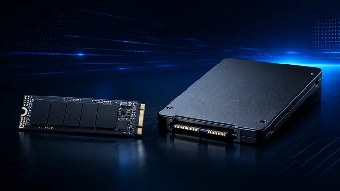
Install the M.2 SSD
Installing the main M.2 drive before the motherboard goes into the case is usually easier. Check which slot is preferred for the system drive and whether installing an M.2 device disables or shares bandwidth with another port.
- Remove the M.2 heatsink or retaining mechanism if present.
- Remove any protective film from the thermal pad only when you are ready to reinstall the heatsink.
- Insert the SSD into the slot at the angle shown in the manual.
- Lower and secure the drive with the screw or tool-less latch.
- Reinstall the heatsink with the thermal pad contacting the drive correctly.
Prepare and install CPU cooling
Cooler installation varies significantly. Follow the cooler manual for socket hardware, mounting pressure, pump connection and fan orientation.
Tower or top-down cooler
Install the required backplate/brackets, apply thermal paste if needed, mount the heatsink evenly and connect the fan to CPU_FAN. Check RAM and side-panel clearance.
AIO cooler
Plan the radiator position, fan airflow and tube routing. Mount the radiator securely, install the pump/block and connect the pump and fans to the headers specified by the manufacturer.
Some cooler cold plates or thermal pads ship with a plastic protective layer. Leaving it installed can cause immediate thermal problems.
Prepare the PC case
Remove both side panels, take out accessory boxes and inspect the motherboard tray. Confirm that standoffs exist only where the motherboard has mounting holes.
A misplaced standoff can short against the back of the motherboard. Keep only the standoffs that correspond to actual mounting holes.
Install the motherboard
If the rear I/O shield is not integrated, install it before lowering the board into the case. Hold the motherboard by its edges, align the I/O area and standoffs, then start all screws before tightening them gradually.
- Lower the motherboard onto the correct standoffs.
- Confirm no cables are trapped underneath.
- Install mounting screws loosely at first.
- Tighten until secure without excessive force.
- Route the CPU EPS cable near the top of the board before access becomes crowded.
Install the power supply
Orient the PSU fan toward a ventilated opening, normally the filtered bottom intake when the case provides one. For modular units, connect only the cables required by the build before access becomes tight.
Two modular cables can look identical while using different pinouts at the PSU end. Use the cables intended for the exact power-supply model.
Install the graphics card
- Remove the required case expansion-slot covers.
- Open the retention latch on the primary PCIe x16 slot.
- Align the GPU and press it straight into the slot until fully seated.
- Secure the card to the case.
- Add an anti-sag support if the card is large and the case/card design benefits from it.
- Connect the required GPU power cable completely.
Check high-power connector routing. Keep enough room between the GPU power plug and the side panel to avoid forcing an immediate sharp bend at the connector.
Connect power, front I/O, fans and case cables
This is where the motherboard manual becomes especially valuable. Front-panel connectors can be small and their pin layout differs among boards.
Main motherboard power connection.
Seat until fully latchedDedicated processor power near the top edge of the motherboard.
Do not confuse with PCIeMain CPU-cooler fan header used by BIOS monitoring.
Connect before first bootDedicated pump header when specified by the cooler and motherboard manuals.
Follow cooler instructionsPower switch, reset switch and indicator LEDs.
Use the board pinoutFront USB connectors; align keyed headers carefully.
Avoid bent pinsFront headphone and microphone connection, usually routed to the lower board edge.
Match the keyed plugGraphics-card power connection using the required cable type.
Fully seat the connectorCable-management strategy
Route cables behind the motherboard tray where possible, but do not make the first build cosmetically perfect before testing. Keep cables away from fan blades, avoid blocking major airflow paths and leave enough slack to service components later.
Assembly stage 10First boot and BIOS setup
Before fitting the side panels, perform a final connection check. Connect the monitor to the graphics card when a dedicated GPU is installed, connect the keyboard, switch on the PSU and press the case power button.
The first boot can take longer than later boots, especially while a DDR5 platform performs memory training. Give the system time before repeatedly interrupting power.
What to verify in BIOS/UEFI
- Confirm the CPU model is detected correctly.
- Confirm the full installed memory capacity appears.
- Confirm the system SSD is detected.
- Check CPU temperature to make sure the cooler is making proper contact and operating.
- Update BIOS if required for compatibility or an important fix, following the board manufacturer's instructions.
- Enable the appropriate XMP or EXPO profile if desired, then test stability.
- Confirm boot order before installing the operating system.
If the system becomes unstable, a methodical approach makes it much easier to identify whether memory tuning, a BIOS option or another change caused the issue.
Install Windows and drivers
After hardware validation, install the operating system from a prepared USB drive. Then install system updates, chipset/platform drivers and the graphics driver from official sources. Check Device Manager or the operating-system hardware list for missing devices and monitor CPU/GPU temperatures under load.
DiagnosisTroubleshooting a PC that does not boot
| Symptom | First checks |
|---|---|
| No power at all | Wall power, PSU switch, 24-pin ATX, CPU EPS and front-panel power-switch pins. |
| Fans spin, no display | Monitor input, cable connected to GPU, GPU seating, GPU power and motherboard diagnostic LEDs. |
| Memory warning LED | Reseat RAM, test one module in the recommended slot, clear CMOS if appropriate and allow memory training. |
| CPU warning LED | CPU EPS cable, socket installation, BIOS support and cooler mounting pressure. |
| CPU temperature rises very quickly | Cooler contact, protective film, thermal paste, fan/pump connection and pump operation. |
| SSD not detected | M.2 seating, SATA data/power, disabled or shared ports and BIOS storage settings. |
Simplify the system when troubleshooting. Test with one memory module, only essential storage and minimum USB devices. Reducing variables makes diagnosis much faster.
Example OPCBleu AM5 gaming configuration
This example shows how compatible component categories can come together. Always re-check final case dimensions, BIOS support, power requirements, included accessories and current availability before ordering.
An 8-core AM5 processor for a modern gaming and productivity configuration.
View product →Motherboard · AM5 / DDR5MSI B850 Gaming Plus WiFiAn ATX AM5 motherboard with DDR5 support and integrated wireless connectivity.
View product →GPUMSI GeForce RTX 5070 Ti 16G MLG EditionA performance-focused graphics card with 16GB of graphics memory for demanding gaming.
View product →PSU · 850WMSI A850GLS MLG EditionA modular 850-watt 80 PLUS Gold power supply for a high-performance gaming build.
View product →CaseMSI PANO 130R MLG EditionA mid-tower gaming chassis for a modern component layout.
View product →Cooling · 360mmMSI CORELIQUID A17 MLGA 360mm all-in-one liquid CPU cooler for a performance-oriented system.
View product →PC building FAQ
Is building a first gaming PC difficult?
It is manageable for a beginner who verifies compatibility, follows component manuals and works one subsystem at a time. Do not rush connectors or use excessive force.
How long does a first PC build take?
Several hours is normal. Cable routing, reading manuals and troubleshooting can take as long as physically installing the main parts.
Should I test the motherboard outside the case?
It is optional but useful for complex or expensive builds. A basic bench test can confirm CPU, RAM and GPU can reach BIOS before full installation.
Do I need to buy thermal paste?
Many coolers include paste or ship with it pre-applied. Check the cooler before adding more.
How tight should motherboard and cooler screws be?
Secure, not excessive. Follow the manufacturer's mounting instructions and stop once the hardware is firmly seated.
Should I update BIOS before installing Windows?
Only when required for CPU compatibility or when the update addresses an important issue relevant to the build. Follow the motherboard manufacturer's process exactly.
Where should I connect the monitor?
When a dedicated graphics card is installed, connect HDMI or DisplayPort to the graphics card rather than the motherboard video outputs unless you intentionally need integrated graphics.
When should I finish cable management?
Route cables sensibly during assembly, but do the final tightening and cosmetic work after the PC has successfully booted and passed basic tests.
How much RAM should a new gaming PC have?
32GB is a strong all-around target for many 2026 gaming builds, while 16GB remains workable for lighter systems and 64GB+ is better suited to heavier production workloads.
How should I choose PSU wattage?
Start with the graphics-card manufacturer's system recommendation, include CPU and other component demand, then choose a quality PSU with the correct connectors and reasonable headroom.
Build methodically, then optimize
Compatibility, patient installation and one-step-at-a-time testing matter more than assembly speed. Verify each subsystem before moving on and the first boot becomes much easier to diagnose—and much more likely to succeed.